



In the process of precision metal machining, I often encounter design drawings that feature very sharp internal corners, deep and narrow grooves, or cavities with completely right angles. While these designs may seem reasonable in a 3D model, they are directly limited by tool geometry in actual CNC machining.
1. Physical Limitations of Tool Diameter
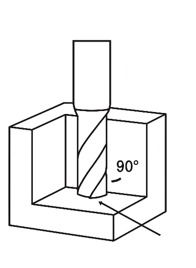
Tools are not infinitely thin; they always have a diameter. For example, the minimum diameter of a common end mill is about 1mm (thinner tools are prone to breaking). This means:
- Internal corners of cavities cannot be machined to a perfect right angle and can only be "milled" into rounded corners.
- The deeper the groove, the worse the tool's rigidity, increasing the risk of vibration and deformation.
2. Rules of Thumb for Rounded Corner Design
Based on our practical experience, if the cavity depth is 9mm, it is recommended that the internal corner radius be designed to be ≥3mm (approximately 1/3 of the depth). This allows the tool to enter smoothly without excessive wear during machining.
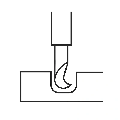
3. Deep Grooves and Tool Rigidity
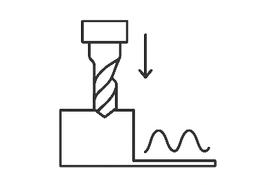
Many designers prefer to design grooves that are both deep and narrow. However, it is important to understand that the longer the tool, the worse its rigidity, making it more prone to bending during cutting, which can lead to:
- Decreased dimensional accuracy at the bottom of the groove.
- Poor surface finish.
- Even tool breakage, increasing costs.
4. Recommendations for Designers and Procurement
Considering the geometric limitations of tools during the drawing phase brings several direct benefits:
- Designs are easier to implement, reducing modification and communication time.
- Avoiding additional costs due to "unmachinable" designs.
- Improving delivery efficiency.
This is why many clients in Europe and the U.S. pay special attention to rounded corners and groove widths during design, while some domestic factories and designers often overlook these aspects.
Practical Conclusion:
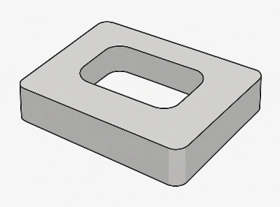
In precision machining, tool geometry dictates whether a design can be manufactured. By following the simple principle of "corner radius ≥ 1/3 of cavity depth, and avoiding overly deep/narrow slots," many machining issues can be avoided.
Mid's experience
At Mid, we apply this principle early in the process by reviewing customer drawings and suggesting radius and slot optimizations before machining begins. This not only prevents costly redesigns but also aligns with the expectations of many European and U.S. manufacturers, who value efficient manufacturability, stable quality, and reliable lead times.


