



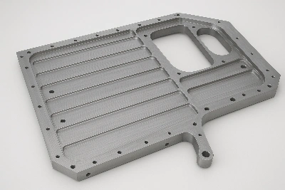
When you mill a wing skin or fuselage frame from a monolithic plate, the part looks rigid on screen but behaves like a spring on the machine. Hours of cutting, uneven heat, and stress release can move thin walls by tenths of a millimeter-enough to fail assembly. The only way to hold spec is to plan for the movement and compensate in real time.
Why It's Hard
Large swept area, thin walls: High material removal rates create temperature gradients; thin ribs respond quickly to heat input.
Long cycle times: Tool, spindle, and fixture drift from thermal growth-even if the machine is "warm."
Residual stress release: As pockets open up, panels "breathe," causing local spring-in/spring-out.
Failure Modes We See
Post-cut springback that pushes skin thickness out of tolerance.
Local waviness on ribs/stiffeners from step-over heat accumulation.
Hole/slot position drift when features are cut before the surrounding stock is stabilized.
Process Controls That Work
Real-time temperature monitoring: Bonded RTDs on the fixture + spindle thermal model; alarms trigger feed override and dwell/cool-down windows.
Machine compensation: Dynamic tool length/scale compensation tied to machine thermal mapping; closed-loop probing to re-zero critical datums mid-cycle.
Zoning strategy: Divide the panel into thermal zones. Rough opposite zones in alternation (A↔C, B↔D) to balance heat and stress release.
Cutting strategy: High-efficiency roughing with light radial engagement, consistent chip thickness, and controlled step-down to avoid hot spots.
Coolant & air management: High-flow flood + directed air knives to evacuate chips from deep pockets; reduce recutting heat.
Stabilization passes: Semi-finish to near net, allow a timed relaxation, re-probe, then finish with light, cold passes only after temps return to baseline.
Fixturing: Vacuum + pin-locators with compliant supports under thin bays; torque-limited clamping to prevent "printing" and distortion.
Case Study: One-Piece Wing Web, 2.8 m × 1.1 m, Al-Li Plate
A European airframe supplier required rib thickness ±0.05 mm and slot true position ≤0.08 mm after full machining. Initial trials showed up to 0.18 mm springback in the thinnest bays.
What changed:
Added four fixture RTDs and a spindle thermal sensor; created a temperature gate at ΔT ≤ 2.5 °C between fixture and stock before finishing.
Reordered toolpaths into a cross-hatch zoning plan; inserted 12-minute equalization pauses per quadrant.
Switched to 6-flute variable-pitch end mills for semi-finish and reduced radial engagement to 12–15% with higher feed to keep chips thin and cool.
Mid-cycle probing of six control datums; applied +0.0006 scale in X locally (machine compensation) for the final pass.
Result: Maximum post-cut deviation dropped to 0.046 mm on ribs and 0.06 mm on slot position-green across all inspection points.
Practical Checklist (Save This)
Place temperature sensors on fixture, stock edge, and machine column.
Define thermal hold points before critical finishing.
Alternate roughing zones; never empty adjacent bays sequentially.
Force chip evacuation; re-cut chips = heat.
Semi-finish → relax → re-probe → finish light.
Log tool wear vs. temperature; preempt finishing with fresh tools.
Verify CMM with on-machine probing targets to catch drift early.
Subtle but Important
Thermal compensation is not a single feature; it's an orchestration of sensing, sequencing, and light finishing. Done right, large thin-wall aerospace panels come off the machine meeting spec without heavy hand-rework-and they stay in tolerance after cool-down.


