



As we all know, hard anodizing will lead to thickness increased of product.Therefore, proper thickness of oxide film is crucial to meet customer size requirements.
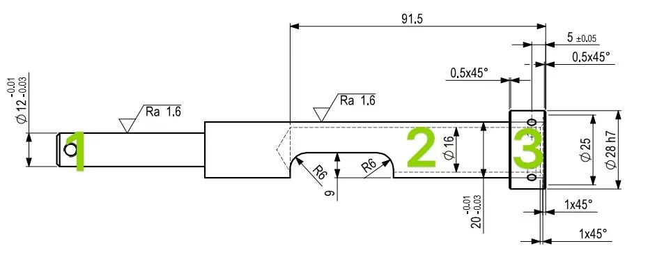
This article uses the shaft above photo as an example to explain how to control the thickness of the oxide film so that the final product size reaches the expected value.
Two steps only for hard anodizing of this shaft:
Step 1: Shaft semi-finished product size should obey to principle of "smaller outer layer thickness and larger inner hole diameter",prior to hard anodizing.
This is because a shaft inner hole diameter size decreased as increasing of oxide film thickness after hard anodizing,which resulting in an unqualified product. While following above principle will avoid this fault and obtain a finished product customer required.
Step 2: a definite production control range should be given to the mechanics for that customer can get a desired finished product size after hard anodizing.
A specific production control range analysis for this shaft as follow:
As drawing said,hard anodized with PTFE impregnation, thickness 40±5μm. This will be 35/3--45/3(11.667μm~15μm) for oxide film growth thickness when shaft hard anodized.And the oxide film growth thickness is 0.0117~0.015 in millimeter.
So , the calculation formula for the production control dimension range given to the mechanic is:
Production control size = drawing size - oxide film growth thickness size x2
That is: production control size = drawing size - [(0.0117~0.015mm) x2] = drawing size - (0.0234~0.03mm)
NOTE:
There are 2 sides of oxide film growth thickness,so double counting in calculation.
If a most accurate final size wanted to get,the minimum value of the oxide film growth thickness should be taken.And 0.02mm is the best choice.
Three parts consist this shaft,and each part control range is as follow:
Marked 1 in photo,the upper and lower line dimensions of this are 11.97~11.99, that is, the production control dimensions are:(11.97~11.99mm)-0.02mm=11.95~11.97mm
Marked 2 in photo,the upper and lower line dimensions of this are 19.97~19.99, that is, the production control dimensions are:(19.97~19.99mm)-0.02mm=19.95~19.97mm
Marked 1 in photo,the upper and lower line dimensions of this are 27.979~28mm(tolerance value H7 combined with tolerance fit value query), that is, the production control dimensions are:
(27.979~28mm)-0.02mm=27.959~27.98mm


